Design ideas can be communicated in many different ways.The most common method of communicating ideas is through drawings and sketches. These can be used to communicate to clients, end users, manufacturers and other designers or experts, to name a few.Designers use also very often sketches to communicate to themselves.
Sketching ideas on paper helps them to visualize products more fully and examine problem areas better. It also frees up their minds, allowing them to develop new ideas: EG. PREHISTORIC CAVE PAINTING, RENAISSANCE PERSPECTIVE, ABSTRACT PAINTING, PERSPECTIVE DRAWING, 3D DRAWINGS, DIGITAL ALTERARED PHOTOGRAPH.
Sketching ideas on paper helps them to visualize products more fully and examine problem areas better. It also frees up their minds, allowing them to develop new ideas: EG. PREHISTORIC CAVE PAINTING, RENAISSANCE PERSPECTIVE, ABSTRACT PAINTING, PERSPECTIVE DRAWING, 3D DRAWINGS, DIGITAL ALTERARED PHOTOGRAPH.
(Introduction to the unit and activities of views--->LINK HERE: Theory&Activities)
ACTIVITIES Nº1.
1.1.- Match the correct word of this definitions:a) We use it to measure angles: Protractor
b) We use it to draw parallel and perpendicular lines: Set square
c) We use it to draw arcs and circumferences: Compass
d) We use it to measure the length of lines: Rule
ACTIVITIES Nº2.
2.1. Using the computer, draw the following arches using AutoCAD.(open here)2º METHODS:
Technical drawing can be made using three different methods:
- a) SKETCH: It´s a freehand drawing where you put your ideas on a paper quickly and maintains its proportions and incorporates its dimensions. In this case we don´t have to use rulers, only with a pencil.
- b) TECHNICAL DRAWING (LAYOUT): It´s a drawing where you have been using rules, set square, compass (instruments) to give an exact picture. In this case if we use a computer to drawing, then this method is called GRAPHICS (CAD=Computer Addes Desing). Here are several types of these methods:
- ORTOGRAPHIS PROJECTIONS: "VIEWS": Very useful because they offer the necesary information to construct an object. "Views" are the faces of an object. An object have six faces, but normally it is only necesary draw three of them: FRONT VIEW, PLAN VIEW (overhead viwe) and SIDE VIEW. To draw them you have to look perpendicular at the face, in a parallel plane, and they have to be in specific positions in relation to each other so that we can interpret them. (SlidesShare about views---> LINK HERE: VIEWS). (SlideShare:4773 orthographic View more presentations from nayakq
- ISOMETRIC/OBLIQUE SYSTEM. "3-Dimensional Drawing", excellent for communication the parts of an object together. It shows us the whole object instead of its separate views.
- CONICAL PERSPECTIVE. The object looks the same as we really see it. The lines int the drawing comes from one viewpoint (like the human eye) called "vanishing point".
ACTIVITIES Nº3:
3.1.In your blog, match and complete the sentences:- With a pair of compasses, we can draw arcs and circumferences.
- With a set square, we can draw pararallel and perpendicular line.
- With a protactor, we can measure angles.
- With an oblique system, we can represent together of the views of an object.
- With the conical system, we can represent an object like we see it.
(...measure angles. /...represent together of the views of an object. /...draw arcs./...draw parallel lines. / represent an object like we see it.)
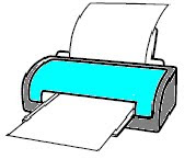
3.2. Sketch with guidelines in M.PAINT: A PRINTER and A RECEPTABLE of this sheet--->Link here: Skecth
3.3. Draw TECHNICAL DRAWING using M.PAINT of the PLAN VIEW and FRONT VIEW of a pen with the lid on.
3.4. In the before exercise, do you need to draw the SIDE VIEW? Why?
e) Draw in M.PAINT the VIEWS of the 8 exercicies at the end of this slides--->LINK HERE: VIEWS
3.5. Draw your first capital letter using the CONICAL PERSPECTIVE CONICAL with M.PAINT.
3º MEASUREMENTS.
The measurements or dimensions are used to understand the overall size of a drawing. They have three items:
- EXTENSION LINES: It should not touch the drawings and must be extended beyond the drawing.
- DIMENSION LINES: It´s an arrow.
- FIGURES: It´s the number that show the real dimension, it´s draw over the arrow.
Scale is the expression of the “MEASUREMENT OF THE DRAWING divided by MEASUREMENT ACTUALLY”. We need draw the object with different scales when it is not possible draw your layout to full size. There are three types:
- NATURAL SCALE or FULL SIZE: The object fit properly into your notebook, so you draw it in the same dimensions that it actually is. 1:1
- INCREASE SCALE. When you enlarge the object that it actually is. E.g. a ring, a tack, a chuck, a nut, etc. 2:1
- REDUCCTION SCALE: When you reduce the object than it actually is because it´s very large and not fit into your sheet. E.g. 1:10
ACTIVITIES Nº4.
4.1.What scale would you use to draw a SPOON on A4 paper? 1:14.2.What scale would you use to draw a BOOKSHELF on A4 paper? 1:4
4.3.What scale would you use to draw a NEEDLE on A4 paper? 2:1
4.4. Copy the sentences in your Blog and complete then with the apropiate words:
a) An object is smaller thant the drawing in an enlarged scale.
b) W use a scale 1:1 to read the measurement of a scale.
c) The drawing is smaller tha the object in 1:2 scale.
Develop of the unit on the website TECNO12-18: http://www.tecno12-18.com/pag/temas/teg.htm
ACTIVITIES Nº5
5.1. Draw the views of the picture:
ACTIVITIES Nº6
1.- Listening and make out it on MS_Paint: LINK.
2.- Draw this road. Add a sky with clouds adn some grass onthe verge of the road.Add some trees. What sort of perspective is it?
ANNEXES:
* Develop of the unit on the website TECNO12-18: http://www.tecno12-18.com/pag/temas/teg.htm
* Futher information in the webside: www.dibujotecnico.com


